


Contact person:
Ing. Zdenko Hušek, zdenko.husek@mdj.sk, +421 948 376 665
Description of functions/solutions
The program is used to measure and evaluate the induced voltage waveform.
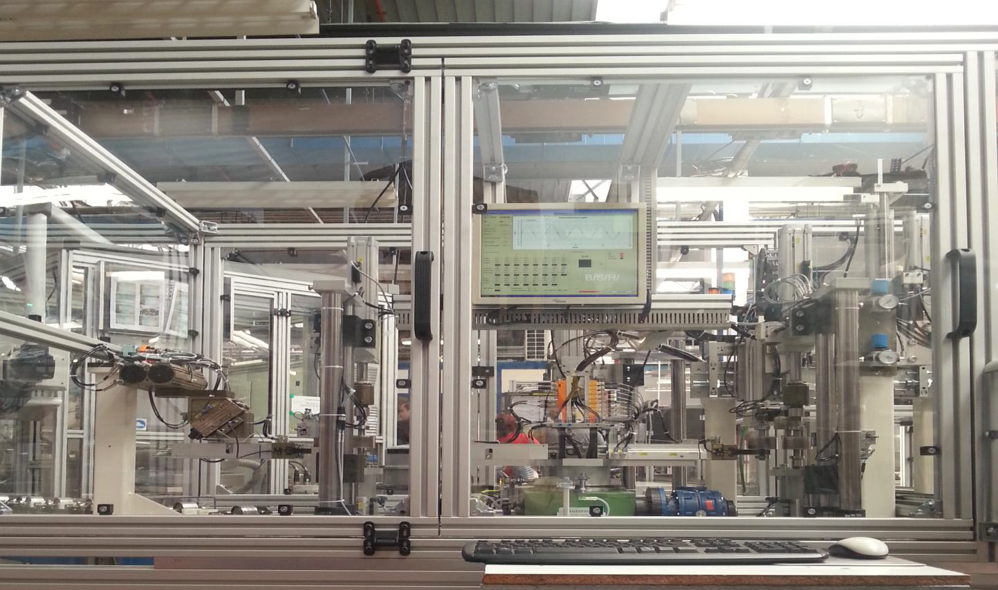
For the measurement itself, one part of the stator coil, at a predefined distance from the rotor, connected to the analog input of the "Measurement interface box" is used.
The program is designed to run unattended and with automatic communication with the PLC controlling the station. The measurement and evaluation time for the rotor is a maximum of 6 seconds.
Activities performed
- Software programming
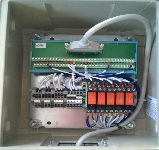
- Manufacture and delivery of local cabinet for connection of measurements
- Supply of hardware (computer with measurement card)
DESCRIPTION OF THE SOLUTION
AUV basic parameters:
- Supported OS Windows XP Professional and higher
- the induced voltage measurement program starts automatically after Windows OS start-up and runs without the need for operator guidance
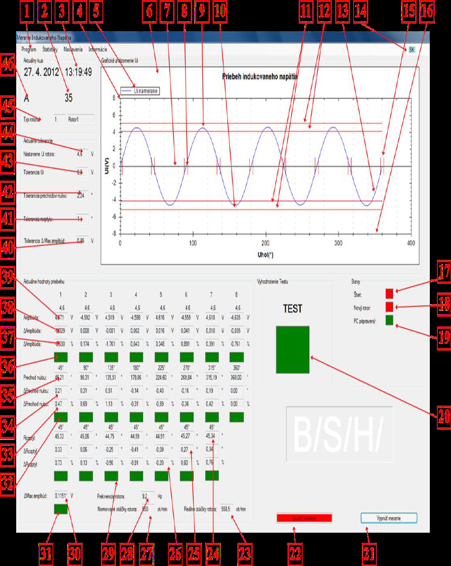
- the software includes a graphical user interface (GUI) for visualization of the measured values and analysis of the measured induced voltage of the tested rotor type
- the software communicates with the measurement card PCIE-1816 and with its help obtains from the PLC discrete inputs/outputs for starting the measurement/sending the test result and an analogue input for obtaining the measured induced voltage waveform from the process. Communication with the control PLC is provided by digital inputs/outputs and for sending the currently measured rotor type from the PLC, communication is provided by RS232
- the software displays the acquired data in a tabular graphical form
- the software provides archiving of relevant data in predefined form and also archiving of obtained graphs
The maximum possibility of direct measurement of induced voltage, even with induced voltage measurement tolerance, is ±10V. DI/DO signals are 24V when using the "Measurement connection box".
AUV basic parameters:
- GUI block
- communication and waveform block
- measurement analysis block
- data archiving block
- software displaying the acquired data in tabular graphical form
- statistical evaluation block
- other functionalities and requirements
The configuration block allows the authorized user to change the program settings:
- change the tolerances of the maximum and minimum induced voltage, the dispersion and tolerances of the zero point location, set the working times of the three working shifts
- add new users with access to the configuration, - change the language of the application
- switch on and off the saving of waveform images to save DB space
- initialize the DB
- manually set the type of rotor to be measured and the induced voltage values
APPLICATION AREAS
- Measurement of rotor magnetization quality
- Measurement of compliance with the correct composition procedure